AUTOCAD FUNDAMENTALS 104 (Move, Mirror and Copy )
STEPS
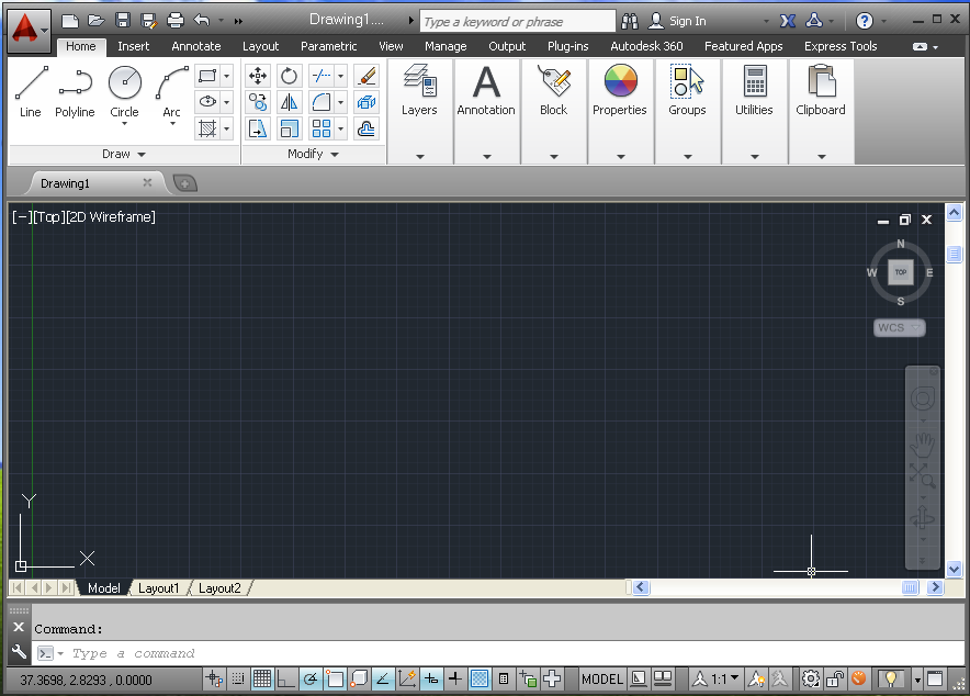
1)Start AutoCAD.
Save as “car-model-1”.
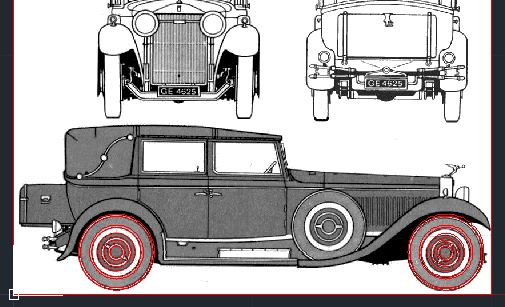
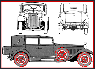
2) Download the image below.
Save as “car-model.gif”

3) Import the image into your AutoCAD Drawing.
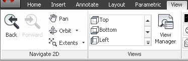
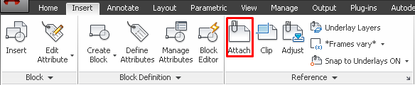
3-1) Go to Ribbon: Insert/Reference/Attach.
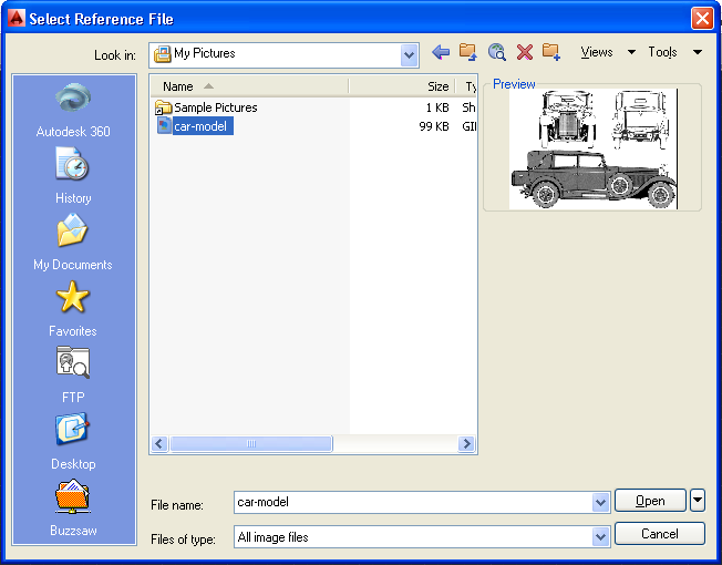
3-2) Find the “car-model.gif” file.
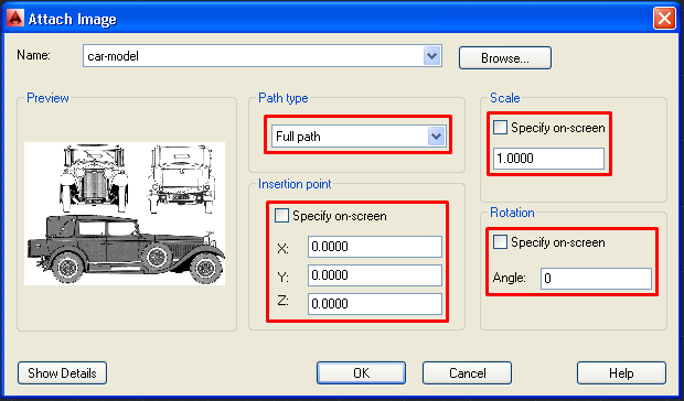
3-3) Set the following Attach Image values.
3-3-1) Path Type: Full Path
3-3-2) Insertion point: Specify on-screen (No), X=0, Y=0, Z=0
3-3-3) Scale: Specify on-screen (No), 1
3-3-4) Rotation: Specify on-screen (No), 0
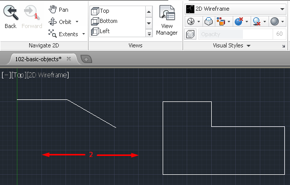
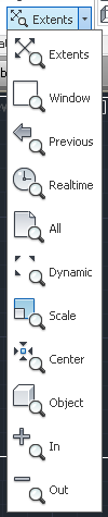
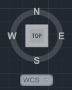
3-3-5) Click the Zoom Extent button on the Navigation Bar to show the whole image on the drawing space.

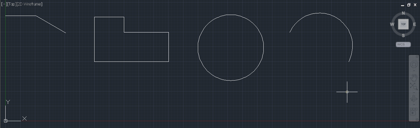
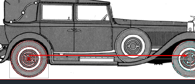
4) Draw the Rear Wheel.
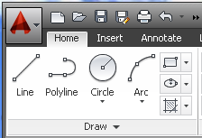
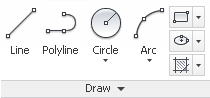
4-1) Go to Ribbon, Select: Home/Draw/Circle/3-Point.
Look at the example on the help dialog window.
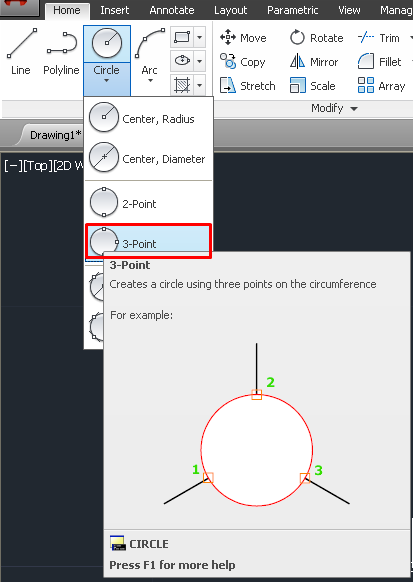
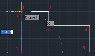
4-2) Click on three points as shown below.

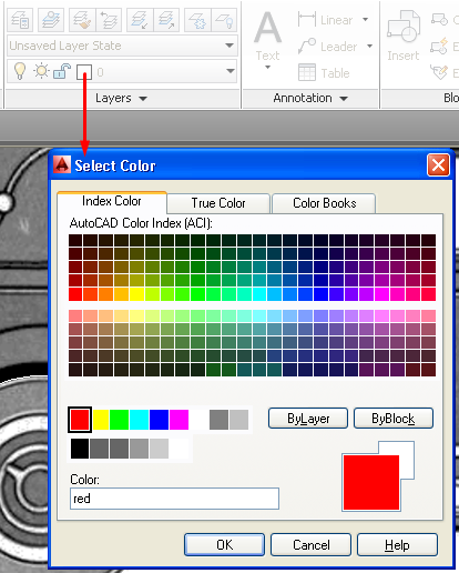
4-3) Change the layer color from White to Red so that you can see the drawing clearly.

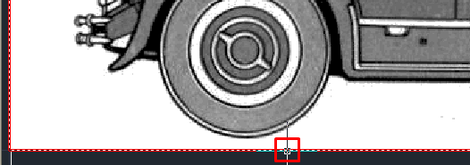
5) Draw the Center Point of the Rear Wheel.
5-1) Select Point Tool.
Go to Ribbon: Select Home/Draw/Point

5-2) Activate Snap function.
Turn On Object Snap.
Turn On Center.

5-3) Click the center of the Circle object.

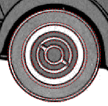
6) Draw the other circular parts of the Rear Wheel.
6-1) Select Circle (Center, Radius)

6-2) Draw circle objects.

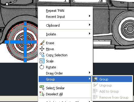
7) Group the Circle Objects.
7-1) Select the circles.

7-2) Right-Click and Select Group/Group.
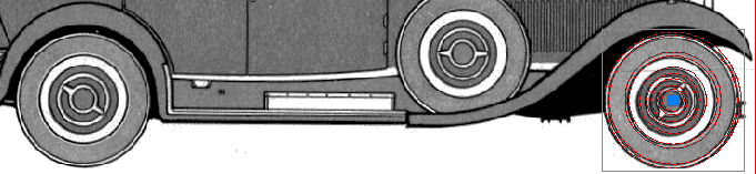
8) Move Wheel Object Group to the Front Wheel.
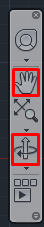
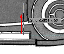
8-1) Turn On the Ortho Mode.

8-2) Select the Group.
Find the grip. (Blue Node)

8-3) Click the Grip and move it to the right until the group is nicely placed on top of Front Wheel.
8-4) The Wheel Object now has moved from Rear Wheel to Front Wheel drawing.
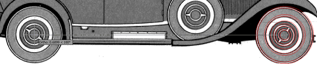
9) Create a Mirror Copy of the Wheel Object.
To create a mirror copy, we need to know the mid-point between the Front and Rear Wheel. We will draw a Line to show us that point.
Info:
Before you start, make sure that you have activated Snap function and turned on the Mid-Point.
|

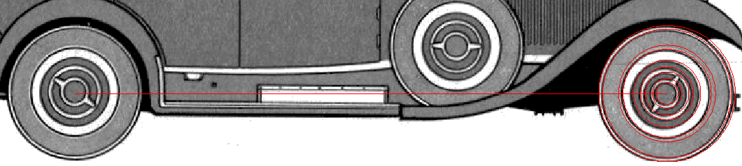
9-1) Draw a Line from the center point of the Wheel Object to the center of the Rear Wheel drawing.
9-2) If you can’t see the Line, set the Image Frame property to have Background Transparency.
9-2-1) Click the border of the Image Frame.
9-2-2) When the Context Tab appears in the Ribbon, select Background Transparency.
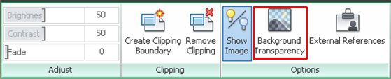
9-2-3) The Line should be visible now.
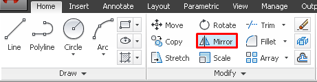
9-3) Select Mirror Tool.
9-4) Select the Wheel Object. Press ENTER.
9-5) Bring the mouse to follow the Line towards the Rear Wheel drawing until the mid-point symbol appear. Click that point.
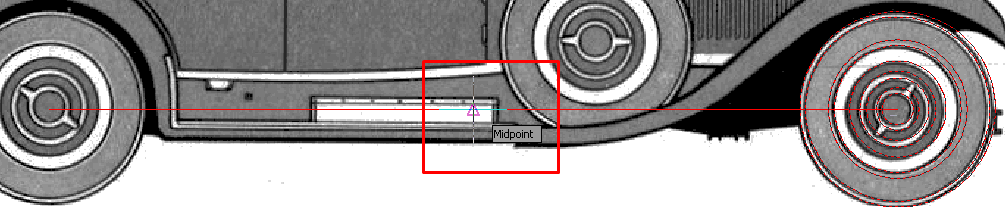
9-6) Move the mouse upward a little bit and click.
9-7) The Command Line will prompt you “Erase source objects?”. Press Enter to accept the default answer, No.

9-8) The Mirror Copy is created exactly on the Rear Wheel drawing.

9-9) Delete the Line object as it is not needed anymore.
10) Create a Normal Copy of the Wheel Object
To create a Normal Copy, we have to select the object, specify Base Point and define the Target Point.
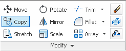
10-1) Go to the Ribbon. Select Home/Modify/Copy.
10-2) Click the Rear Wheel Object and press ENTER.
You will see the prompt below in Command Line.

10-3) Click the Center point of the Rear Wheel Object.

10-4) Click on the Spare Wheel drawing location and press ENTER to quit from Copy function.

10-5) Outcome:
DOWNLOAD: car-model-1.dwg
---